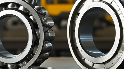
Choosing the right Roller Bearing begins with the machine, not the catalogue. Load direction, speed, temperature, contamination, and available space all shape the decision. A tapered roller bearing may handle combined radial and axial loads effectively. A cylindrical design may suit heavy radial loads at higher speeds. Small differences matter. A 0.5 mm clearance error can change heat generation, noise, and service life.
Industry research supports careful selection. MarketsandMarkets identifies automotive, industrial machinery, aerospace, and energy as major bearing demand sectors. Fortune Business Insights also reports continued growth in the global bearing market, driven by automation, electric vehicles, and renewable-energy equipment. These trends increase expectations for lower friction and longer maintenance intervals. Yet market growth does not make every bearing suitable. ISO 281 calculates rating life, but real operating conditions can shorten it. Lubrication, misalignment, installation quality, and contamination remain decisive.
Henry Timken, the founder of The Timken Company, expressed the core purpose simply: “Reduce friction, increase efficiency.” His principle still applies, though it is incomplete today. Efficiency alone cannot guide selection. A bearing must survive the actual shaft, housing, lubricant, and duty cycle. That is where many recommendations become too convenient. Engineers should compare calculated life with field conditions, inspect failure evidence, and question optimistic assumptions. The right Roller Bearing is not always the largest or most expensive option. It is the one that delivers reliable performance under measured conditions.
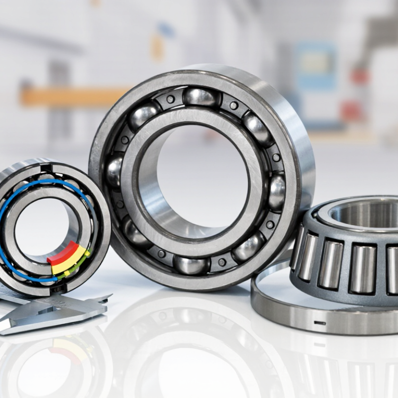
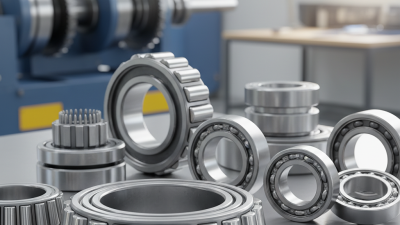
Roller bearings work by replacing sliding contact with rolling contact. Their operating principle is simple, but selection is not. Cylindrical rollers mainly carry radial loads. Tapered rollers handle radial and axial loads together. Spherical rollers tolerate shaft misalignment. Needle rollers fit tight spaces, although they need accurate raceways and careful lubrication.
The contact shape matters. Line contact gives roller bearings high load capacity, but it also increases sensitivity to contamination and alignment errors. ISO 281:2007 defines basic rating life, L10, as the life that 90% of identical bearings can reach under identical conditions. That figure is useful, not magical.
Actual life changes with speed, lubricant viscosity, temperature, mounting, and debris. In field inspections, a blue raceway often signals overheating, while flaking suggests fatigue or poor lubrication.
I usually begin with load direction, speed, available space, and expected misalignment. Then I check static safety and calculated rating life. A bearing with a higher load rating may still fail early if its seal cannot protect the lubricant. This is where selection gets uncomfortable. Catalog calculations rarely capture every vibration or assembly mistake. ISO 15243:2017 classifies common damage modes, including wear, corrosion, and fatigue. That standard helps connect marks on a failed bearing with operating conditions. Sometimes the honest answer is uncertain. A cleaner installation may outperform a theoretically stronger bearing.
Choosing a roller bearing starts with the load, not the catalog bore. Measure radial, axial, and shock loads at the shaft, then record duty cycles. A steady 4 kN load needs a different calculation from repeated 4 kN impacts. ISO 281:2007 defines basic rating life, L10, as the life reached by 90% of identical bearings. Its equation uses p = 10/3 for roller bearings, making load errors costly. For example, doubling the load cuts calculated life to roughly 11% under that exponent. That number is useful, but not destiny. Misalignment, contamination, and poor lubrication can dominate.
Speed changes the decision. Check the bearing’s reference speed, limiting speed, cage design, lubricant, and heat path. These figures are not interchangeable; test laboratories may define them differently. Use ISO 15243:2017 damage classifications when inspecting flaking, smearing, or brinelling.
For oscillating motion, calculate the small-angle amplitude and frequency, rather than treating it as rotation. For reversing loads, verify clearance and preload through the full travel. In field checks, a cool housing can mislead; raceway marks may reveal short-stroke false brinelling. I would leave margin for dirt, vibration, and imperfect installation. The difficult part is admitting the input data may be incomplete.
Choosing a roller bearing starts with material, not catalog dimensions. In field inspections, heat tint, fretting marks, and gray raceways often reveal a mismatch. Through-hardened bearing steel suits high loads and moderate temperatures. Stainless steel resists moisture, but usually sacrifices some load capacity. Ceramic rolling elements reduce electrical-current damage and support high-speed operation. They also cost more and need careful fit control.
Design must follow the actual load path. Cylindrical rollers handle heavy radial loads. Tapered rollers accept combined radial and axial forces. Spherical rollers tolerate housing misalignment, although they may generate more heat. Seal selection matters in dusty or wet equipment. A tight seal protects grease but can increase drag. ISO 281:2007 calculates basic rating life. Its L10 value represents a 90% survival probability under stated conditions. That is useful, not perfect. Lubrication, contamination, mounting, and shock can reduce real life sharply.
The U.S. Department of Energy’s industrial motor-system assessments place motor systems near 70% of industrial electricity use. Small bearing friction can therefore matter across large fleets. Still, energy savings should not dictate material alone. A low-friction option may fail early in abrasive dust. I have seen specifications copied from older machines without checking today’s duty cycle. That shortcut deserves challenge. Record speed, peak load, temperature, washdown exposure, and shaft tolerance before ordering. Then compare steel grade, internal clearance, cage design, seals, and lubrication against measured conditions. Sources: ISO 281:2007; U.S. Department of Energy, Industrial Motor Systems Market Assessment Report.
Compare the primary load directions supported by common roller-bearing designs before selecting the material, cage, lubrication, and sealing arrangement.
Best suited to high radial loads and relatively high radial stiffness. Standard separable designs generally do not carry primary axial load.
Provide high radial load capacity in a small radial envelope. Axial guidance normally requires separate thrust components.
Designed for combined radial and axial loads. Pair adjustment is commonly used to control internal clearance or preload.
Support heavy radial loads, moderate axial loads, and housing or shaft misalignment within the bearing's permissible range.
Choosing a roller bearing requires more than matching its load rating. Seals, lubricant, speed, temperature, and contamination must work together. A sealed bearing can resist dust and moisture, but excessive sealing may increase friction and heat. Small details matter.
Inspect the operating area before selecting a seal type. Fine powder may require stronger protection than occasional water spray. Check shaft alignment, housing fit, vibration, and expected temperature changes.
Measure the heat. If the bearing runs near its temperature limit, ordinary grease may lose consistency or oxidize quickly. Use a lubricant approved for the actual speed and temperature range, not simply the one already available.
Lubrication quantity also deserves careful attention. Too little grease creates metal contact, while too much can cause churning and overheating. Relubrication intervals should reflect load, speed, moisture, and cleanliness.
In field inspections, technicians often find damaged seals caused by installation tools, not poor bearing design. That possibility is easy to overlook. A clean workspace, correct mounting force, and proper shaft finish improve reliability.
Still, calculations can miss real operating changes. A machine may run lightly during testing, then face shock loads during production. Record noise, temperature, and vibration after installation, and compare those readings with the bearing’s specified limits.
How to Choose the Right Roller Bearing?
A suitable roller bearing starts with a precise fit. Measure the shaft and housing, rather than trusting old drawings. A loose fit can cause creeping, fretting, and heat. An overly tight fit may reduce internal clearance. Check the actual load, speed, temperature, and shock conditions. These details often expose an unsuitable selection.
Alignment deserves equal attention. Even a strong bearing can fail under angular misalignment. Inspect shaft runout, housing seats, and mounting faces during installation. Use calibrated tools when possible. A small error can create uneven contact across the rollers. In field inspections, unusual vibration often appears before visible damage. Listen for changes, but do not rely on sound alone.
Service life depends on more than rated capacity. Contamination, poor lubrication, and repeated overload can shorten it sharply. Select grease or oil for the operating temperature and speed. Keep seals clean, and prevent moisture from entering during maintenance. Record vibration, temperature, lubrication dates, and replacement history. This makes gradual changes easier to recognize. Still, maintenance plans are not perfect. Inspection intervals may need adjustment after seasonal or load changes. A bearing that looks clean may already have hidden fatigue. Small observations matter.